Color
Models for MapInfo
Jacques
Paris
jacques@paris-pc-gis.com
April 2002
This
presentation of color models is done in the perspective limited by the ways
MapInfo uses color. It cannot be taken as a scientific basis and in my attempts
at translating various sources I may have introduced some errors or biases. Any
correction or comments are welcome.
6
- Conversions between RGB and various models
7
- MapBasic Code for some Conversion Functions
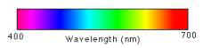
Each
color of the visible spectrum corresponds to a single wavelength. Light, white
light in particular, is formed by a combination of wavelengths and when it goes
through a prism, a beam of light breaks into a rainbow of colors with different
intensities. The descriptions of a precise color would require thus very
involved means way too complex for use in real life.
Color
models have been developed to facilitate color transmission and reproduction.
They are used for two different purposes: as ways to depict as precisely as
possible colors as they can be perceived by man, or as means to rebuild colors
artificially, mainly with electronic means or printing machinery.
The
conception, development and refining of descriptive scientific models is a very
involved scientific undertaking. The works of the CIE (Commission Internationale
de l’Éclairage) in particular are impressive (http://www.cie.co.at/cie/).
A good practical reference is http://www.adobe.com/support/techguides/color/colormodels/cie.html
But
they are of no immediate use for the user of computer applications because he
deals mainly with two interfaces, the computer screen and the printed sheet and
that application of the “scientific” models to these equipments is not
easily done, or is directly impossible practically.
A
tool may impose its own way on the user. The color monitor has been developed
using a technology for showing colors by using pixels made of 3 “phosphors”
emitting each a different color, the human eye recombining those basic colors to
“see” one unique spot of a “complex” color.
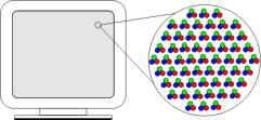
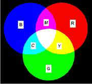
This
is the basis of the RGB model: adding RED, GREEN, and BLUE (RGB) with
varying intensities will create all the colors of the rainbow.
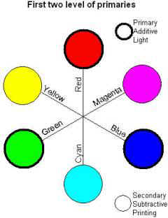
As these colors when added together at their maximum intensity will
produce White, they are called additive primaries, also light
primaries.
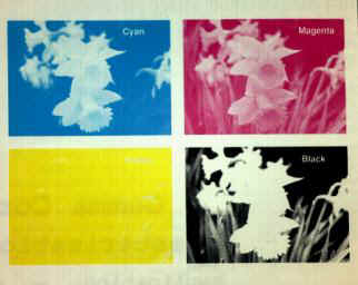
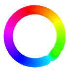
Let
us imagine laying down all the colors around in a circle. When moving away from
a primary, this one starts to play a small role while the approaching primary
will increase its own. Having gone around for 180 degrees, there is none of the
original primary left; this color called a complementary primary is made in
equal part of the primaries on each side, and of none of the opposite primary
 If
the primary colors are also called light, it is because they are used to create
“colored lights”.
If
the primary colors are also called light, it is because they are used to create
“colored lights”.
The
secondary colors are those used to mix paints which color come from reflectance
and not from luminescence; hence their alternate naming as printing primaries
(allusion to inks) and subtractive primaries (they are “extracted from” an
image to form the films used in printing).
The
explanation that follows is taken from http://www.adobe.com/support/techguides/color/colormodels/rgbcmy.html
and is another illustration of how tools can impose some particular ways to
handle “reality”.
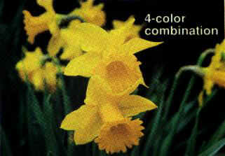
“The CMY model used in printing lays down overlapping layers of varying percentages of transparent cyan, magenta, and yellow inks. Light is transmitted through the inks and reflects off the surface below them (called the substrate). The percentages of CMY ink (which are applied as screens of halftone dots), subtract inverse percentages of RGB from the reflected light so that we see a particular color:
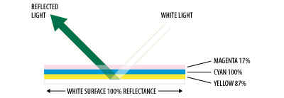
In the illustration above, a white substrate that reflects 100% of the light is printed with a 17% screen of magenta, a 100% screen of cyan, and an 87% screen of yellow. Magenta subtracts green wavelengths, cyan subtracts red wavelengths, and yellow subtracts blue wavelengths from the light. The reflected light, then, is made up of 0% of the red wavelengths, 44% of the green wavelengths, and 29% of the blue wavelengths. [...]
In theory, the combination of cyan, magenta, and yellow at 100%, create black (all light being absorbed). In practice, however, CMY usually cannot be used alone. Due to imperfections in the inks and other limitations of the process, full and equal absorption of the light isn't possible; thus a true black or true grays cannot be created by mixing the inks in equal proportions. The actual result of doing so results in a muddy brown color. In order to boost grays and shadows, and provide a genuine black, printers resort to adding black ink, indicated as K. Thus the practical application of the CMY color model is the four color CMYK process.”
To
the RGB model, we can add now the CYM model, at least the basis of that model
that is implemented generally by using a fourth dimension Black and is thus
referred as CYM(K) or CYMK model .
The
RGB model has certainly some very valid technical justification, but it is not
the way people play generally with colors. One would imagine rather that they
start with a basic mix to which they add white to lighten it or black. Several
attempts have been made to replicate in some way that practical way to
“paint”. A family of models is based on the RGB color cube and some
transformation of the space reference system, such as using the White-Black
diagonal of the cube (the gray scale) as one axis. MapInfo is using in some
circumstance the HSV model, but as its “cousin” HSL is also in wide
use, its differences to HSV are worth noting.
The
RGB model is based on the use of the 3 primary colors RED, GREEN, and BLUE and
of their additive property; any color is obtained by the addition of the basic
components in specific proportions.
The
RGB model is used in a television or computer monitor. The colored spots of a TV
screen emit three colors, and the sum of these colors determines the impression
to the eye.
The
values for each component vary from 0 to a maximum that depends upon the
“size” of the binary variable used to store them. On a 8-bit machine, the
maximum is of 15 and the number of different colors of 16^3=4096; on a 16-bit
platform, each component can reach 255 and the combinations of the 3 exceeds 16
million colors (256^3=16 777 216).
If
the three components are 0, the result is black. If they all are at their
maximum, the color is white. If they are all equal, the color will be gray; they
are thus only 256 shades of gray, including pure white and pure black.
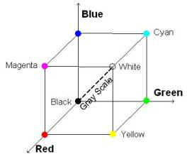
The
domain of variation of the components can be represented in 3 dimensions by what
is called a “Color Cube”. Its “skeleton” allows to show in particular
the “path” of the gray scale
One can see only 3 faces of the cube at the time; to view all its faces, the cube is presented split into two, the outside faces fronting the viewer on top, the opposite exposing their internal side (luckily they are transparent!) at the bottom.
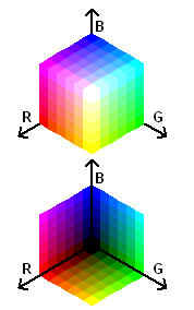
This drawing was produced with a MapBasic program; it contains 6 levels in each component, which means there are 216 different colors in this table. With a higher number of levels, the number of colors would exceed the maximum of 256 allowed in a single table and some will not be “exact” but duplicates from the “first” 256 instead of corresponding to their specified components. (see “Limitations in the number of different colours” in the main document)
A color can be defined by using the numerical values of its components. The following table shows three different ways to express the values: decimal 0-1.0, percentage 0-100%, or byte value, an integer from 0 to 255. If MI uses exclusively the 0-255 integer notation, it should not hide the fact that color is a “continuous” phenomenon and that using integers to define its components replaces a linear continuous increase by a limited number of equal steps, however tiny these steps be.
|
Color name |
R |
G |
B |
|
Red |
1.0 – 100% – 255 |
0 |
0 |
|
Green |
0 |
1.0 – 100% – 255 |
|
|
Blue |
|
|
1.0 – 100% – 255 |
|
Cyan |
0 |
1.0 – 100% – 255 |
1.0 – 100% – 255 |
|
Magenta |
1.0 – 100% – 255 |
0 |
1.0 – 100% – 255 |
|
Yellow |
1.0 – 100% – 255 |
1.0 – 100% – 255 |
0 |
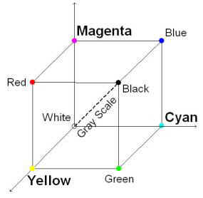
The CMY
model is a simple transposition of the RGB model in its own space. Its
representation as a schematic cube is practically the save, save for some
“rotation” among the colors.
But this
is a simplified version of the model that involves a fourth dimension: the color
Black. If two variants are shown, it is to point at the situation that in some
contexts Black enters in play only when the color is Gray, variant CMY(K), while
in the full model Black can enter into play with any color, variant CMYK.
The
reason for that distinction comes from the conversion problem, the CMY(K) is the
variant one must use with a conversion algorithm, because there does not seem to
be any mathematical procedure to make a full conversion. It is even written that
production of CMYK images (to make films for printing) is a machine dependent
operation. One thing seems sure, MI will never handle colors with a full CMYK
interface, it will at the most create some CMYK output that could be used only
for what it was intended originally: printing.
The
example that follows is a classic of an image and its 4 components.
The H
stands for Hue. That dimension comes from an organization of the colors starting
with original six primaries and generalized to a continuous circle. A hue
indicates the position of the color on the circle by the angle it “makes”
with the origin 0 for Red. There are different ways to expressed that angle, in
degrees or in percentages or ratios always relating the actual degrees to the
full 360 degrees circle.
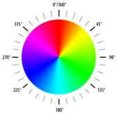
Hue is the position relative to
the origin (red=0) measured in degrees.
|
|
degrees |
ratios |
Percent. |
|
Red |
0,
360 |
0,
1.0 |
0,
100. |
|
Yellow |
60 |
.167 |
16.7 |
|
Green |
120 |
.333 |
33.3 |
|
Cyan |
180 |
.500 |
50.0 |
|
Blue |
240 |
.667 |
66.7 |
|
Magenta |
300 |
.833 |
83.3 |
The S is
for Saturation (also called Chroma) that measures “the strength or purity of a
color. Saturation represents the amount of gray in proportion to the hue,
measured as a percentage from 0% (gray) to 100% (fully saturated). On the
standard color wheel, saturation increases from the center to the edge.” [1]
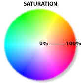
“Saturation
refers to the dominance of hue in the color. On the outer edge of the hue wheel
are the 'pure' hues. As you move into the center of the wheel, the hue we are
using to describe the color dominates less and less. When you reach the center
of the wheel, no hue dominates. These colors directly on the central axis are
considered de-saturated. These de-saturated colors constitute the
grayscale; running from white to black with all of the intermediate grays in
between. Saturation, therefore, is the dimension running from the outer edge of
the hue wheel (fully saturated) to the center (fully de-saturated), perpendicular
to the value axis.” [2]
The last
dimension is L for lightness-darkness. How light or dark a color is, is referred
to either as the color lightness or value. In terms of a spectral
definition of color, value describes the overall intensity or strength of the
light. That dimension varies from 0 (darkest) to 100 (brightest) along an axis
perpendicular to the “color wheel”.
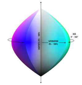
The three dimensions put
together gives a volume shaped like a cone, some reducing it to a hexacone
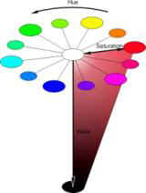
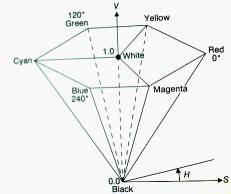
but more likely to be more like that image

In order
to appreciate the impact of choices in this model, one can use the “slicer”
application available on http://ftp.lecad.uni-lj.si/pub/vaje/resitve/4.15/hsv.html;
it produces “ground plans” or color disks for a given Value (in this model
disks have all the same size) and “side plans” or slice along the value axis
for a given Hue. Here are some examples:


hue 90º
hue 225º hue 345º
Or is it
HSL?. A variant of the HSV model, or a different handling of the color cube? I
am including that model in this document to give a fuller coverage of that class
of models even though it would not be required in the stricter perspective of
the use of color in MapInfo. Its description will be more limited.
Hue
has the same definition as in the HSV model
Saturation
is the degree to which the hue differs from a neutral gray. From 0% (no color
saturation) to 100%, (fullest saturation of a given hue at a given percentage of
illumination)
Lightness
is the level of illumination. From 0% (no light > appears black) to 100%
(full illumination > appears white).
It is
easy to imagine the representation of the volume of the color space as a simple
adaptation of the RGB color cube. The vertical axis of that volume corresponds
to the White/Black diagonal of the cube and the section through the middle of
that axis can be viewed as the projection on that plan of the 6 other corners of
the cubes, another way to “build” the color wheel.
Theoretically
described as a “double hexacone” (compared to the single hexacone for HSV),
it is more like an ellipsoid, rounded at its girth, pointed at the extremities.
At 50% lightness, the colors are their “fullest” (below they appear darker,
above lighter).
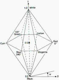
A
section along the main axis of the double hexacone volume would yield something
like that next image.

6 - CONVERSIONS BETWEEN RBG AND VARIOUS MODELS
Color
codes in MI are based on the RGB model where values of the 3 components define a
unique number. Component values fit in a byte variable and consequently their
are integral values ranging from 0 to 255. A null value indicate the total
absence of that component, 255 its full contribution.
The
general formula tying together components and code is
RGB
= (65536 * R) + (256 * G)
+ B
A
MapBasic function computes the code from the components:
RGB(red,
green, blue)
To
see how it works, open the MapBasic window (menu Options > Show MapBasic
window), type the following line
print
RGB(123,234,100)
and run the command (keep cursor on the line and <Enter>). The result is displayed in the Message window (that is open automatically if it is not already open).
If
RGB combines the 3 components in one number, the reverse conversion from RGB
code to R, G, B components is not provided for in MapInfo. The user that needs
to specify a color in a style requester when he knows only its RGB code must
calculate the three components with these successive formula:
R
= RGB \ 65536
G
= (RGB - R*65536) \ 256
B
= RGB - R*65536 - G*256
\
stands for “integral division” and returns the integral part of the
quotient.
The
code for the function RGBComp implementing those equations is given in 7-1. A
simple translator demo tool using that function is also available as
RGB2R_G_B.MBX in Nu_ColorFun.zip.
As mentioned already, there does not seem to be a way to migrate from RGB to CMYK in a full manner. There are some partial transformations such as Bill Thoen used in is HexCell application. The tabular part of the results list the equivalence between the two systems
Even
if the column heading is CMYK, one can see there is no Black in the rows. The
formula used for the translation is a standard application of general equations
and as it is not able to calculate the level of black used in combination with
colors, it sets it equal to zero. An extension of the formula when R=G=B not
implemented in Hexcell version 2.00 is to set C=M=Y=0 and calculate K with the
general formula using any color component.
R,
G, B <> C, M, Y
The
general formulas are
Cyan
= 1 – Red
Red = 1 - Cyan
Magenta
= 1 – Green
Green = 1 – Magenta
Yellow=
1 – Blue
Blue = 1 – Yellow
They
must be adapted to the MI context, such as
Cyan
= Int((255 – Red) / 2.55 + 0.5)
Magenta
=
Int((255 – Green) / 2.55 + 0.5)
Yellow
= Int((255 – Blue) / 2.55 + 0.5)
A
glance at the formula shows that while a RGB component ranges from 0 to 255, the
corresponding CMY component varies from 100 to 0. There are then fewer colors
defined by CMY than by RGB. However this is only for a simplified model (no
Black) and if only integral values are used; in reality, there is no theoretical
constraints at using decimal values, the general formulas indicating indeed the
use of a decimal 0 –1 value.
R, G, B <> C, M, Y, K
The
general formulas are not symmetrical as in the previous case. From RGB to CMYK
they are, once adapted to MI
Black
= minimum(255 – Red, 255 – Green, 255 – Blue)
Cyan
= (255 – Red – Black) / (255 – Black)
Magenta
= (255 – Green – Black) / (255 – Black)
Yellow
= (255 – Blue – Black) / (255 – Black)
C,
M and Y range from 0 to 1, and Black from 0 to 255; it must be recalibrated
after C, M, Y are calculated.
The
CMYK to RGB conversion formulas that give R, G and B in the 0-255 range are:
Red
= INT((1 - minimum(1, Cyan * (1 – Black) + Black))*255 + 0.5)
Green
= INT((1 - minimum(1, Magenta * (1 – Black) + Black))*255 + 0.5)
Blue
= INT((1 - minimum(1, Yellow * (1 – Black) + Black))*255 + 0.5)
According
to some authors[3],
“these cheap and nasty transforms may be fine for printing a bar chart or for
spot colour on a newsletter but for even semi-critical applications the colour
reproduction is poor”. They go on to recommend much more involved procedures
calling first on the “CIE tri-stimulus values” before converting to CMYK,
and that is way beyond the scope of this document.
I have implemented as part of “Palette Maker” two procedures to convert the component values between the two systems. They are MapBasic adaptations of scripts I found on the web. Besides the changes due to the language differences, I had to introduce calibration factors to the output of RGB2HSV and to the input to HSV2RGB to reflect the differences in the ranges between those used by MI and in the original code.
I would stress here the possible variation in the underlying color model used to establish the conversion algorithm. Similar to HSV are the HSL but also HLS, HBS, HSB. It is most important to make sure of the type of model before adopting the procedures or the code that is offered.
Among potential sources are:
http://m3.polymtl.ca:3829/SColor.i3.ToHSV#ToHSV the origin of these scripts is described as “Copyright (C) 1992, Digital Equipment Corporation. Last modified on Sat Nov 28 1992”.
http://www.joochan.com/hsv-hls_rgb.html a Japanese site with luckily the code in clear Pascal
The results of these functions are numerically very close to those displayed by MI in its “Pick Color” requester; early tests showed some differences only on the H component. However, using the output of one as the input to the other will show more noticeable differences between original input and final output.
There are several causes to these
differences, one, probably the most important, is due to the use of integral
variables and operations to deal with a continuous phenomenon. Rounding errors
can become compounded; I have not the expertise in this domain to find a fully
satisfactory solution. The MS article says it clearly: “There
are potential round-off errors throughout this sample. ((0.5 + x)/y) without
floating point is phrased ((x + (y/2))/y), yielding a very small round-off
error. This makes many of the following divisions look strange.”
The second cause of discrepancies is probably the use of different ways to express the values of the components, i.e. their ranges of variations: in the HSV model, they are 0_240 in the MI context, 0_1 for H and S, 0_255 for V in the DEC procedures, something else in others. That requires the use of scaling factors that adds to the rounding problem already mentioned.
I was not able yet to consult the Foley and Van Dam reference and I would not be able to describe the exact calculation principles. I have found “second hand” explanations[4] that do not entirely satisfy me
1 - Find the maximum and the minimum of R,G,B
2 - S=(Max – Min) / Max
V = Max
3
- R’
= (Max – R) / (Max – Min)
G’
= (Max – G) / (Max – Min)
B’ = (Max – B) / (Max – Min)
4
- If
S=0, the hue is undefined (monochrome color), otherwise
if R = Max
and G = Min >>
H = 5 + B’
and G <> Min >>
H = 1 – G’
if G = Max
and B = Min >>
H = 1 + R’
and B <> Min
>>
H = 3 – B’
if R = Max
>>
H = 3 + G’
otherwise
>>
H = 5 – B’
I have some reservation about the last two conditions (typos in the transcription?), the first one about R should probably be about B because the situation (B = max) is not covered by the first 4 conditions and it is incomplete because it does not differentiate between the two situations (expressed in two ways: R min or not, or G not min or min)
5
- H
= H * 60
S and V have a 0-1 range, H 0-360 (degrees)
range
HSV
> RGB
1 - Hex= H / 60
2
- primary
color = INT(Hex)
secondary color = Hex – primary color
a = (1 – S) * V
b = (1 – (S * secondary color)) * V
c = (1 – (S * (1 – secondary color))) * V
3
- if
primary color =
0
>>
R = V
G = c
B = a
1
>>
R = b
G = V
B = a
2
>>
R = a
G = V
B = c
3
>>
R = a
G = b
B = V
4
>>
R = c
G = a
B = V
5
>>
R = V
G = a
B = b
Computational
procedures for RGB<>HSL
From http://blas.mcmaster.ca/~monger/hsl-rgb.html:
Notice
the specific scales that are used for input and output.
1 - Convert the RBG values to the range 0-1
Example: from the video colors page, colorbar red has R=83%, B=7%, G=7%, or in this scale, R=.83, B=.07, G=.07
2 - Find min and max values of R, B, G
In the example, maxcolor = .83, mincolor=.07
3 - L = (maxcolor + mincolor)/2
For the example, L = (.83+.07)/2 = .45
4 - If the max and min colors are the same (i.e. the color is some kind of grey), S is defined to be 0, and H is undefined but in programs usually written as 0. (all is done)
5 - Otherwise, test L.
If L < 0.5, S=(maxcolor-mincolor)/(maxcolor+mincolor)
If L >=0.5, S=(maxcolor-mincolor)/(2.0-maxcolor-mincolor)
For the example, L=0.45 so S=(.83-.07)/(.83+.07) = .84
6 - Compute
If R=maxcolor, H = (G-B)/(maxcolor-mincolor)
If G=maxcolor, H = 2.0 + (B-R)/(maxcolor-mincolor)
If B=maxcolor, H = 4.0 + (R-G)/(maxcolor-mincolor)
For the example, R=maxcolor so H = (.07-.07)/(.83-.07) = 0
7 - To use the scaling shown in the video color page, convert L and S back to percentages, and H into an angle in degrees (ie scale it from 0-360).
8 - From the computation in step 6, H will range from 0-6. RGB space is a cube, and HSL space is a double hexacone, where L is the principal diagonal of the RGB cube. Thus corners of the RGB cube; red, yellow, green, cyan, blue, and magenta, become the vertices of the HSL hexagon. Then the value 0-6 for H tells you which section of the hexagon you are in. H is most commonly given as in degrees, so to convert
H = H*60.0
9 - If H is negative, add 360 to complete the conversion.
1 - If S=0, define R, G, and B all to L (all is done)
2 - Otherwise, test L.
If L < 0.5, temp2=L*(1.0+S)
If L >= 0.5, temp2=L+S - L*S
In the colorbar example for colorbar green, H=120, L=52, S=79, so converting to the range 0-1, L=.52, S=.79, so temp2=(.52+.79) - (.52*.79) = .899
3 - Compute
temp1 = 2.0*L - temp2
In the example, temp1 = 2.0*.52 - .899 = .141
4 - Convert H to the range 0-1
In the example, H=120/360 = .33
5 - For each of R, G, B, compute another temporary value, temp3, as follows:
for R, temp3=H+1.0/3.0
for G, temp3=H
for B, temp3=H-1.0/3.0
if temp3 < 0, temp3 = temp3 + 1.0
if temp3 > 1, temp3 = temp3 - 1.0
In the example, Rtemp3=.33+.33 = .66, Gtemp3=.33, Btemp3=.33-.33=0
7 - For each of R, G, B, do the following test:
If 6.0*temp3 < 1, color=temp1+(temp2-temp1)*6.0*temp3
Else if 2.0*temp3 < 1, color=temp2
Else if 3.0*temp3 < 2, color=temp1+(temp2-temp1)*((2.0/3.0)-temp3)*6.0
Else color=temp1
In
the example,
3.0*Rtemp3
< 2 so R=.141+(.899-.141)*((2.0/3.0-.66)*6.0=.141
2.0*Gtemp3
< 1 so G=.899
6.0*Btemp3 < 1 so B=.141+(.899-.141)*6.0*0=.141
8 - Scale back to the range 0-100 to use the scaling shown in the video color page
For the example, R=14, G=90, B=14 Color in video
7 - MAPBASIC CODE FOR SOME CONVERSION FUNCTIONS
As mentioned in the text, these functions can certainly be improved in their precision, i.e. in the simultaneous use of integer values and decimal calculations. They may not follow the exact computational procedures due to a different origin of their original codes.
‘==================================================================
‘==================================================================
declare
function rgbcomp(byval rgbcode as integer, rcomp as smallint, gcomp as smallint,
bcomp
as smallint) as logical
‘==================================================================
function
rgbcomp(byval rgbcode as integer, rcomp as smallint, gcomp as smallint,
bcomp
as smallint) as logical
‘
return FALSE if RGBcode out of range
if
rgbcode<0 or rgbcode>16777215 then
rgbcomp=0
exit
function
end
if
rcomp=int(rgbcode/65536)
gcomp=int((rgbcode
- rcomp*65536)/256)
bcomp=rgbcode
- rcomp*65536 - gcomp*256
rgbcomp=1
end
function
‘==================================================================
‘==================================================================
declare
function Rgb2Hsv(byval rgbr as smallint, byval rgbg as smallint,
byval
rgbb as smallint, hsvh as smallint, hsvs as smallint, hsvv as smallint) as
logical
‘==================================================================
function
Rgb2Hsv(byval R as smallint, byval G as smallint,byval B as smallint,
H
as smallint, S as smallint, V as smallint) as logical
'**************************************
'
Input R, G, B, 0-255
*
'
Output H, S, V, 0-240
*
'
Return False for unacceptable R,G,B *
'**************************************
dim
max, min, rr, gg, bb, ht as float
Rgb2Hsv=1
if
R<0 or R>255 or G<0 or G>255 or B<0 or B>255 then
Rgb2Hsv=0
exit
function
end
if
rr=r/255
gg=g/255
bb=b/255
max=maximum(maximum(rr,gg),bb)
min=minimum(minimum(rr,gg),bb)
V=
int(max*240 + 0.5)
if
max <> 0 then
S =
int((max-min)*240/max + 0.5)
else S
= 0
end
if
if
S = 0 then
H
= 0
else
if
rr = max then
ht =
(gg-bb)/(max-min)
elseif
gg = max then
ht = 2 + (bb-rr)/(max-min)
else
ht = 4 + (rr-gg)/(max-min)
end if
end
if
ht=ht/6
if
ht < 0 then ht = ht + 1 end if
H=INT(ht*240
+ 0.5)
end
function
‘==================================================================
‘==================================================================
declare
function Hsv2Rgb(byval hsvh as smallint, byval hsvs as smallint, byval hsvv as
smallint,
rgbr
as smallint, rgbg as smallint,rgbb as smallint) as logical
‘==================================================================
function
Hsv2Rgb(byval H as smallint, byval S as smallint,byval V as smallint,
R
as smallint, G as smallint, B as smallint) as logical
''**************************************
'
Input H, S, V, 0-240
*
'
Output R, G, B, 0-255
*
'
Return False for unacceptable H,S,V *
'**************************************
dim t1, t2, t3, i as smallint
dim
ht, hh, ss, vv, f as float
Hsv2Rgb=1
if
H<0 or H>240 or S<0 or S>240 or V<0 or V>240 then
Hsv2Rgb=0
exit
function
end
if
if
V=0 then
R=0
G=0
B=0
exit
function
end
if
if
H=1 then H=0 end if
hh=H/240
ss=S/240
vv=V/240
i=int(hh*6)
if
S = 0 then
R =
int(VV*255 + 0.5)
G =
R
B =
R
exit
function
end
if
f=hh*6
- i
t1
= int(VV * (1 - SS) * 255 + 0.5)
t2
= int(VV * (1 - SS * f) * 255 + 0.5)
t3
= int(VV * (1 - SS * (1 - f)) * 255 + 0.5)
v=int(vv*255
+ 0.5)
do
case i
case
0
R = V
G = t3
B = t1
case 1
R = t2
G = V
B = t1
case 2
R = t1
G = V
B = t3
case 3
R = t1
G = t2
B = V
case 4
R
= t3
G = t1
B = V
case 5
R
= V
G = t1
B = t2
case else
Hsv2Rgb=0
end
case
end
function
‘==================================================================