Some notes on using offset line patterns
Jacques Paris, 27/04/2002
All the patterns used in these notes have been prepared with "Line Style Editor for MapInfo" available on the MI site. They are all one pixel thickness lines.
Influence of line separation
Line separation is the distance between 2 lines; if one is offset by 2 pixels and the other by 5, their separation is of 3 pixels.
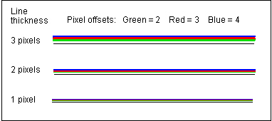
Separation of 1 pixel gives a continuous colored band that could be interesting for an artistic gradation effect but does not help in separate color identification
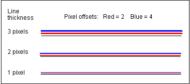
One should use at least a 2 pixel separation (see next image), and that should be sufficient for most applications. It would be possible to create 7 patterns on each side if one wants to leave some space between base line and first offset ("even" offsets from 2 to 14). If no space is required (the base line is not drawn), there can be 8 ("odd" offsets from 1 to 15)
As can be seen in the next image, color separation increases with line thickness. If one pixel lines are somewhat difficult to recognize, color separation is not for much; it is mainly the small size of the line that does not carry much color impact in itself. A 2 pixel thickness has already a good impact.
Notice that distance between lines increases also with line thickness; there is no risk of getting overlapping colors if all the lines have the same thickness. A mixture of line sizes can lead to very poor results, each line distance to the base line being a result of its offset AND of its thickness.
Application to polygons
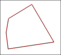
Offset line patterns can also be used with polygons (regions). The drawing direction of the polygon must be know to choose the proper style for creating the line inside or outside the polygon.
Application to "routes"
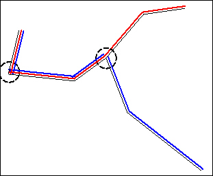
With this simplest example of a 2 route "network", several areas of potential trouble can be detected. In this example we assume that
1 - the routes must be on the same side of the base line; this is in accordance with the possible "directionality" of the routes
2 - they must be as close as possible to that base line; the consequence is that the network and the routes must be broken down in sections at all the junctions
continuity of colored paths
At any branching of routes, a given route may have to "cross over" another one (above image); if we had chosen to inverse the colors in the left section, the red line on the top then will not be in line with the red section to the right. The break would be less visible but there is no guarantee that that result could be reached for all the routes at all the junctions. One possibility to minimize a potential "bad impact" would to hide the junction by a small circle or a symbol suggesting a "transfer" between routes.
"inside" corners
At nodes where the base line forms a "sharp" angle and where the offset line is "inside" the base line, there is a risk that the offset line will not form sharp corners (see the small mess located within the left circle). There does not seem to be a way to prevent that from happening.