Outlining regions with offset line styles
Jacques Paris
Nov 2002
I have found an interesting use for Offset Line Styles as was reported here some time ago (see in the other articles in this section) . The situation is as follows:
The "state" is composed of "municipalities"; the municipalities are regrouped in "regions" (the intention was that a region should follow municipality boundaries, but history and changes in municipalities mostly by fusions have defeated in part the intention). Operational "zones" have been created, that are based mainly on municipalities and region boundaries but not always.
The problem is to show distinctly the three sets of boundaries in a map based on a region but showing also all extensions to it (zones extending beyond the region, municipalities partly enclosed in the zones or in the region).
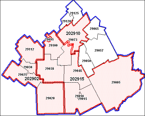
The solution presented here uses different offset styles: the regions are outlined with blue line offset to the left of the base line in the drawing direction (it will be "above" the base line in the MiLiStEd utility) when the polygon is drawn clockwise (that will be outside the region) (see below for a discussion on "clockwise region"). The zones use red lines offset to the right, the opposite of the regions (they will appear to be inside the zones); they also have a light red hatching. The municipalities follow the original trace and are in black. Each "level" is in a different layer.
Click on the maps to get larger images
The first example is for a region that does not have any "extensions". It contains 3 zones and their common borders are clearly visible with the triple line. But also visible is the municipality 29073, slightly above the center that is split between two zones 202910 and 202915. The middle black line (municipality boundary) is missing. Municipalities not included in a zone are also clearly visible.
This region does not take 43023 in its entirety and include a very small part of 42005 officially outside the region (the small triangle between 43023 and 43020). The 102043 zone is almost completely within the region but for its extension to the west where it takes in part an outside municipality (42025).
Maps produced that way carry a much richer visual information that is a real enhancement. They can also be used as an editing tool; situations like those found in the second example may reveal inadequacies in the base maps (changes that have not been recorded in all the maps) or a need for official adjustments to the definitions at all or some of the levels.
CLOCKWISE REGIONS
A line direction is from first node to end node. Left or right of the line is relative to that direction. A South to North line direction implies that West is to the left, East to the right. Line direction can be shown in a mapper by using the Display | Show Line Direction in the Map | Options menu item.
That option is limited to lines and single section polylines or to the first section of multi section polylines. It does not apply to single or multiple polygon regions.
We can define a clockwise polygon one for which the drawing direction of its border is such that the inside of the polygon is to its right (my sister found out that to circle a Buddha statue clockwise she will have to keep it to her right while walking, if not she will get into trouble with the temple priests; same idea).
If a region contains only one polygon, the same definition can apply; if it contains several non-overlapping polygons, the definition must apply to all of them; but if there are overlapping polygons (donut in all shapes and configurations), then the rule becomes more complex.
Let us use the notion of order in a pile. When several polygons overlaps, they must be within each over (they cannot intersect in the case of a region). If we order them in increasing size, we can attach to each one an order by the number of polygons within which it is contained. The largest will of course have the order 1. All the polygons of odd orders will be clockwise, but those with even orders must be counterclockwise.
That reason stems from the fact that only one line style can be used for all the polygons of a region. If it is set to "left=outside of circular donut" for clockwise external polygons (odd order), to get with the same line style the border of internal polygons (even order) inside them (i.e. outside the circular donut), the line direction must be reversed, i.e. the internal polygons must be counterclockwise.
IMPLEMENTATION
The regions that will be used with offset line style must respect the clockwise definition. The AllClock.mbx will create a new table with all the contents and attributes of an original table but with all the regions clockwise. It is available for testing in the BETA section of this site.
The offset line styles used in the example are those available in the MAPINFOW_OFF.PEN available via P. Blanc's paper in this section. The styles are those following the last documented pen in the MI version; the could be number from 119 and up. 119 and 121 are left offset (outside), 120 and 122 right offset (inside). The offset is one pixel for 119 and 120, two pixels for 121 and 122.
Region and zone tables are both set to clockwise. Region pen style was set to left (outside 121) and those for zones to right (inside 122)